With the large-scale equipment and the widespread use of steel casting, ultra-thick plates are more and more widely used in equipment manufacturing.
Flame cutting is the primary process in the production and processing of structural parts, coupled with the irreversibility of flame cutting, the CNC flame cutting process for ultra-thick plates has become an essential technology for large equipment manufacturers. Therefore, it is of great significance to study and master the CNC flame cutting process of ultra-thick plates.
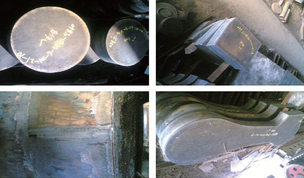
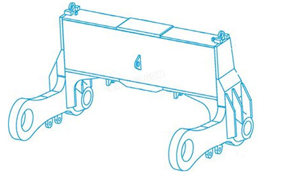
The big bag turntable is an important equipment in the square and round billet project of the steelmaking plant. Due to the large product structure of the equipment, the harsh use conditions, the high production quality requirements and the great difficulty in production, the first is the CNC flame cutting of thick plates, and the large bag rotation Some components of the table use extra-thick steel plates. The thickness of the No. 9 steel plate in the upper connecting rod as shown in Figure 1 reaches 220mm. It is necessary to analyze the cutting characteristics of ultra-thick plates and formulate corresponding measures to ensure the cutting quality of products.
The Characteristics Of Ultra-Thick plates Flame Cutting
- Oxygen and acetylene Due to the generally larger size of ultra-thick plate parts, the total amount of oxygen and acetylene consumed is much higher.In order to complete the cutting of a single part at one time, the CNC cutting of ultra-thick plates must ensure a continuous and stable supply of sufficient oxygen and acetylene.
- The size and mass of the thick plate are large, such as 220mm×2200mm×8000mm, and the mass is about 30t. The quality of a single part is sometimes very large. In Figure 1, the upper connecting rod No. 9 steel plate can have a mass of more than 4t.
- Easy to produce cutting defects In addition to common cutting defects, ultra-thick plates will also produce defects such as cutting opacity.
- Large loss of material scraps Because of the large loss of scraps of ultra-thick plates, it is difficult to reuse scraps.
- Large cutting deformation The steel plate is subjected to large heat, which leads to material shifting deformation when the steel plate is cut, resulting in zero size deviation. Under the action of huge stress, if the steel plate suddenly pops open, it may cause a safety accident. Therefore, it is necessary to formulate the cutting process. Prevent quality and safety problems caused by cutting deformation.
The Cutting Section Of The Ultra-Thick Plate Is Prone To Quality Defects
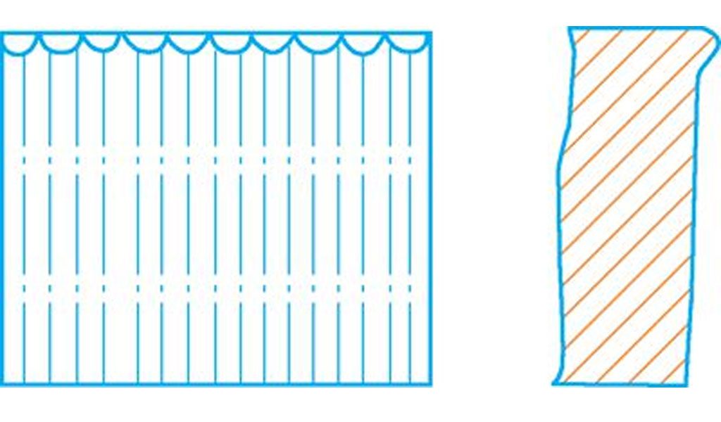
a.Cutting Defects On The Upper Edge
The upper edge is slumped or the water droplet-shaped melted bean string, and the upper edge of the cutting seam melts too quickly, resulting in rounded sagging.The Reason:
- First, there is a thick oxide scale that is refractory on the steel surface;
- Second, the cutting speed is too slow and the preheating flame is too strong;
- The third is that the height between the cutting nozzle and the workpiece is too high or too low, the nozzle size used is too large, and the oxygen in the flame is excessive, as shown in Figure 2.
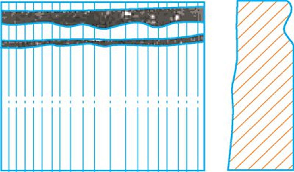
b.Poor Flatness Of Cutting Surface
- There are concave defects below the edge of the cutting section (see Figure 3), and the upper edge has different degrees of melting and slumping, which is due to the high cutting oxygen pressure, or the height between the cutting nozzle and the workpiece is too large; The cutting nozzle is blocked by debris, which causes the air line to be disturbed.
- The roughness of the cutting section is too large, which is caused by the cutting speed being dragged too fast or the impurities inside the steel plate, which affects the forming, as shown in Figure 3.
c.Section Perpendicularity Difference
- The cutting seam is wide at the top and narrow at the bottom or narrow at the top and wide at the bottom. The reason is that the cutting speed is too fast or too slow; the cutting nozzle is blocked by debris, which interferes with the air line; the cutting oxygen is too small or too large, resulting in insufficient metal burning and excessive many.
- Bevel angle occurs because the cutting torch is not perpendicular to the workpiece surface or the air line is not correct.
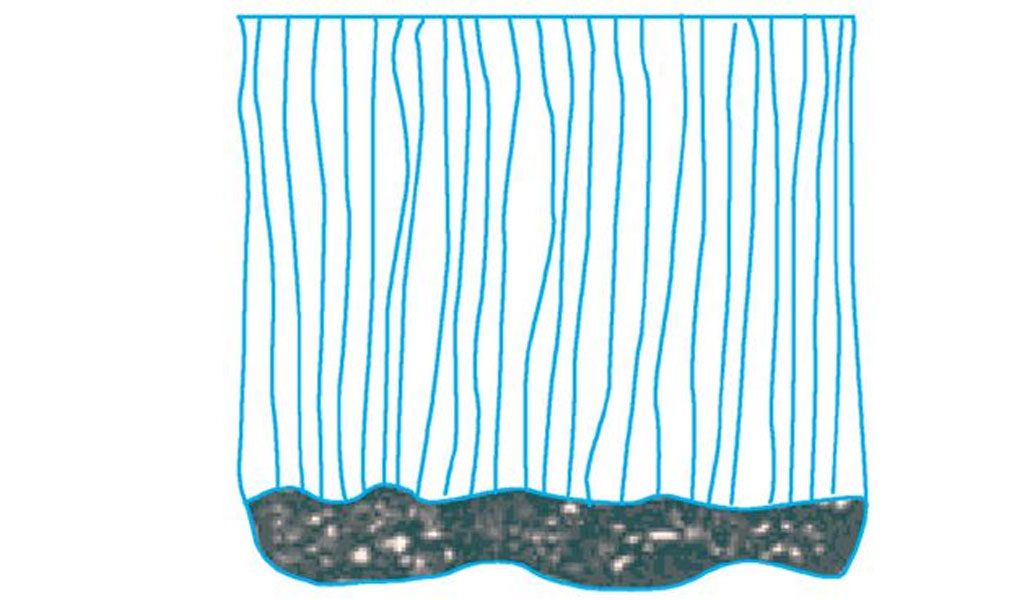
d.Lower Edge Cut Defect
- It is concave near the lower edge and the lower edge is melted into a rounded corner. The reason is that the cutting speed is too fast, the cutting nozzle is blocked or damaged, and the air line is blocked and deteriorated.
- There is slag that is difficult to remove on the cutting section or the lower edge. The reason is that the cutting speed is too fast or too slow, the number of cutting nozzles used is too small, and the cutting oxygen pressure is too low; there is excess gas in the preheating flame, and the surface of the steel plate has The oxide scale is rusted or not clean; the height between the cutting nozzle and the workpiece is too large, and the preheating flame is too strong; too high alloy content will also cause slag on the section and the lower edge (see Figure 4).
e.Crack
Microcracks appear in the cut section or in the heat-affected zone. The reason is that the carbon equivalent of the steel plate is too high and the crack sensitivity is high, but proper preheating and slow cooling measures are not adopted.
f.Deformation
Due to the local heating of the steel plate during cutting, the material movement deformation occurs when the steel plate is cut, so that the size deviation of the cut parts will occur, which will affect the quality of the product.
Cutting Process
(1) Cutting Air Supply System
Due to the large amount of oxygen and acetylene gas supply required for thick plate cutting, it is necessary to ensure stable gas supply for a long time and under high pressure. Some large-scale structural plants have relatively stable oxygen and acetylene gas supply station systems. However, due to various reasons, many units do not have this gas supply system, and mostly use bottled oxygen and acetylene gas. However, the amount of oxygen or acetylene used for a thick plate part is often more than one bottle, and it is interrupted in the middle of cutting the part, and the cutting defect at the interruption will definitely affect the cutting quality; in order to ensure the continuous and stable supply of oxygen and acetylene gas, multiple bottles of gas can be connected in parallel Use to ensure a stable and continuous supply of acetylene.
Make a parallel air supply bag (see Figure 6), use a φ 100mm steel pipe as the air bag, both ends are welded with steel plates, and make 6 air intake pipes and one air outlet pipe on the steel pipe (pay attention to the welding quality to ensure the air bag airtight).
Add air-tight ball valves and take-over devices to each intake and outlet pipe.
When in use, connect 6 bottles of acetylene gas to the air inlet pipe, and connect the air outlet pipe to the air supply pipe of the CNC cutting machine to form a situation that 6 bottles of gas are supplied in parallel. If 6 cylinders of gas are still not enough, you can open three cylinders of gas first. When the use is almost finished, open the other three cylinders of fresh gas, then close the three cylinders of gas that are running out, and replace them with three cylinders of fresh gas. Such a cycle can ensure the continuous supply of air to the air bag.
(2) Cutting Support Frame
Due to the large size and mass of the thick plate, the maximum weight is 30t, and the size and mass of a single part is large, the maximum weight is 4t, so the original CNC cutting machine support frame cannot meet the cutting requirements due to insufficient support force of the slats (see Figure 7a). In addition, due to the strong flame penetration of cutting thick plates, the slats will also be cut off after the parts are cut, causing the parts to collapse the support frame, so that the cutting quality cannot meet the requirements for use. Therefore, in order to ensure the stable support of the support frame, the support frame needs to be transformed. After analysis, research and discussion, it was decided to use waste H-beam as the thick steel plate support frame. specific measure:
- ① Find H-beams with the same width in the waste H-beams.
- ②According to the size requirements of the thick steel plate to be cut, the selected H-beam is used to build a support frame with moderate length and width.
- ③ Check with the marker diagram to ensure that each part will be stably supported after being cut, otherwise add support under the corresponding part.
- ④ Use the CNC machine to cut the nozzle head to find the level.
- ⑤ Level the thick steel plate again and prepare for cutting.
(3) Cutting Program Optimization
First, lead point processing is introduced. The most difficult thing to ensure when cutting ultra-thick plates (up to 220mm thick) is the quality of the incision, especially the position of the introduction and extraction points of the parts, which often cause cutting defects, as shown in Figure 8a and Figure 8b. The cutting point of the thick plate is often not vertical. When the cutting point and the introduction point are coincident, if the cutting line turns at this time, the root will not be cut, and the part will break due to the gravity. In order to prevent similar defects, it can be avoided by optimizing the lead-in and lead-out lines in the cutting program. The specific measures are:
- As shown in Figure 8c, the original program cutting lead-in and lead-out points are on the straight line of the part. When actually cutting, the lead-in and lead-out points should be paused for a while. It does not matter for ordinary thin plates or medium-thick plates, but for super-thick plates, defects will occur.
- Modify the cutting path. The cutting lead-in and lead-out point is best at the corner of the part, cutting from the starting point, cutting directly into the part without stopping at the lead-in point, and directly cutting the part without stopping at the lead-out point after the part is cut. If the part has no corners, as shown in Figure 8d, the track lead-in and lead-out lines are arc lead-in and arc lead-out.
Secondly, the numerical control cutting sequence and cutting direction are studied. Since the parts and the steel plate are heated and expanded at the cutting seam during the flame cutting process, if the direction is not paid attention to during the cutting process, the parts will be lost, that is, the parts will be squeezed away by the expansion force. Causes the part size to be inconsistent with the program size. In order to solve this problem, we analyze according to the analysis: when the steel plate is cut, the weight is light due to the small pressure, resulting in small friction with the support frame and is squeezed away by the expansion force, and the large mass of the steel plate has a high pressure due to the friction force with the support frame. Large and not squeezed out by the expansion force. This has to be taken care of when writing the program, the part is cut with as much mass as possible connected to it.
Finally, the size of the nesting is optimized, which can save a lot of costs. When designing the program, you can spend more time on the optimization of the nesting. Generate the program after confirming that it is correct. The thicker the workpiece to be cut, the torch type, nozzle number, and oxygen pressure should be increased. The oxygen pressure, thickness of the cutting piece, and torch type should be selected according to on-site equipment and cutting experience.
(4) Implement Cutting
Once the steel plate is cut, it should only succeed once. Trial cutting at the discarded corners of the steel plate, adjust the cutting air line, and ensure that the cutting section does not have the above-mentioned defects. Follow up on-site during the cutting process, and deal with the problem as soon as possible.
Conclusion
Through sufficient preparation and strictly formulated cutting process, the cutting of ultra-thick plates has achieved a one-time success, the quality and appearance of product cuts have met the process requirements, and qualified product parts have been cut.